Friday, 21 May 2010

Glossary of automotive

ABS: Anti-lock braking system. An electro-mechanical braking system which is designed to minimize or prevent wheel lock-up during braking.
ACCELERATOR PUMP: A small pump located in the carburetor that feeds fuel into the air/fuel mixture during acceleration.
ADVANCE: Setting the ignition timing so that spark occurs earlier, before the piston reaches top dead center (TDC).
AFTER TOP DEAD CENTER (ATDC): The point after the piston reaches the top of its travel on the compression stroke.
AIR BAG: Device on the inside of the car designed to inflate on impact of crash, protecting the occupants of the car.
AIR CLEANER: An assembly consisting of a housing, filter and any connecting ductwork. The filter element is made up of a porous paper, sometimes with a wire mesh screening, and is designed to prevent airborne particles from entering the engine through the carburetor or throttle body.

Figure 1 Typical type of air cleaner assembly on most of today's cars Typical type of air cleaner assembly on most of today's cars
AIR INJECTION: One method of reducing harmful exhaust emissions by injecting air into each of the exhaust ports of an engine. The fresh air entering the hot exhaust manifold causes any remaining fuel to be burned before it can exit the tailpipe.
AIR PUMP: An emission control device that supplies fresh air to the exhaust manifold to aid in more completely burning exhaust gases.
AIR/FUEL RATIO: The ratio of air-to-gasoline by weight in the fuel mixture drawn into the engine.
ALIGNMENT RACK: A special drive-on car lift apparatus/measuring device used to adjust a car's toe, caster and camber angles.
ALL WHEEL DRIVE: Term used to describe a full time four wheel drive system or any other car drive system that continuously delivers power to all four wheels. This system is found primarily on station wagon cars and SUVs not utilized for significant off road use.
ALTERNATING CURRENT (AC): Electric current that flows first in one direction, then in the opposite direction, continually reversing flow.
ALTERNATOR: A device which produces AC (alternating current) which is converted to DC (direct current) to charge the car battery.

Figure 2 Automotive alternator Automotive alternator
AMMETER: An instrument, calibrated in amperes, used to measure the flow of an electrical current in a circuit. Ammeters are always connected in series with the circuit being tested.
AMP/HR. RATING (BATTERY): Measurement of the ability of a battery to deliver a stated amount of current for a stated period of time. The higher the amp/hr. rating, the better the battery.
AMPERE: The rate of flow of electrical current present when one volt of electrical pressure is applied against one ohm of electrical resistance.
ANALOG COMPUTER: Any microprocessor that uses similar (analogous) electrical signals to make its calculations.
ANTIFREEZE: A substance (ethylene or propylene glycol) added to the coolant to prevent freezing in cold weather.
ANTI-LOCK BRAKING SYSTEM: A supplementary system to the base hydraulic system that prevents sustained lock-up of the wheels during braking as well as automatically controlling wheel slip.
ANTI-ROLL BAR: See stabilizer bar.

Figure 3. Location of a typical anti-roll bar on a McPherson strut suspension  Location of a typical anti-roll bar on a McPherson strut suspension
ANTI-SWAY BAR LINKS: The link pins and bushings that connect the anti-sway bar to the lower control arms in the front or rear suspension.
ARMATURE: A laminated, soft iron core wrapped by a wire that converts electrical energy to mechanical energy as in a motor or relay. When rotated in a magnetic field, it changes mechanical energy into electrical energy as in a generator.
ASE: Acronym for the National Institute for Automotive Service Excellence. ASE is usually affiliated with being a Certified Technician. ASE provides a testing system to recognize a technicians skills and abilities in specific mechanical areas, such as drivetrain, engine performance, electrical, etc.
ATDC: After top dead center.
ATF: Automatic transmission fluid.
ATMOSPHERIC PRESSURE: The pressure on the Earth's surface caused by the weight of the air in the atmosphere. At sea level, this pressure is 14.7 psi at 32°F (101 kPa at 0°C).
ATOMIZATION: The breaking down of a liquid into a fine mist that can be suspended in air.
AWD: All wheel drive.
AXIAL PLAY: Movement parallel to a shaft or bearing bore.
AXLE CAPACITY: The maximum load-carrying capacity of the axle itself, as specified by the manufacturer. This is usually a higher number than the GAWR.
AXLE RATIO: This is a number (3.07:1, 4.56:1, for example) expressing the ratio between driveshaft revolutions and wheel revolutions. A low numerical ratio allows the engine to work easier because it doesn't have to turn as fast. A high numerical ratio means that the engine has to turn more rpm's to move the wheels through the same number of turns.
BACKFIRE: The sudden combustion of gases in the intake or exhaust system that results in a loud explosion.
BACKLASH: The clearance or play between two parts, such as meshed gears.
BACKPRESSURE: Restrictions in the exhaust system that slow the exit of exhaust gases from the combustion chamber.
BAKELITE: A heat resistant, plastic insulator material commonly used in printed circuit boards and transistorized components.
BALL BEARING: A bearing made up of hardened inner and outer races between which hardened steel balls roll.
BALL JOINT: A ball and matching socket connecting suspension components (steering knuckle to lower control arms). It permits rotating movement in any direction between the components that are joined.

Figure 4 Front suspension ball joints Front suspension ball joints
BALLAST RESISTOR: A resistor in the primary ignition circuit that lowers voltage after the engine is started to reduce wear on ignition components.
BATTERY: A direct current electrical storage unit, consisting of the basic active materials of lead and sulphuric acid, which converts chemical energy into electrical energy. Used to provide current for the operation of the starter as well as other equipment, such as the radio, lighting, etc.

Figure 5 A sealed type battery A sealed type battery
BEAD: The portion of a tire that holds it on the rim.
BEARING: A friction reducing, supportive device usually located between a stationary part and a moving part.
BEFORE TOP DEAD CENTER (BTDC): The point just before the piston reaches the top of its travel on the compression stroke.
BELTED TIRE: Tire construction similar to bias-ply tires, but using two or more layers of reinforced belts between body plies and the tread.
BEZEL: Piece of metal surrounding radio, headlights, gauges or similar components; sometimes used to hold the glass face of a gauge in the dash.
BIAS-PLY TIRE: Tire construction, using body ply reinforcing cords which run at alternating angles to the center line of the tread.
BI-METAL TEMPERATURE SENSOR: Any sensor or switch made of two dissimilar types of metal that bend when heated or cooled due to the different expansion rates of the alloys. These types of sensors usually function as an on/off switch.
BLOCK: See Engine Block.
BLOW-BY: Combustion gases, composed of water vapor and unburned fuel, that leak past the piston rings into the crankcase during normal engine operation. These gases are removed by the PCV system to prevent the buildup of harmful acids in the crankcase.
BOOK TIME: See Labor Time.
BOOK VALUE: The average value of a car, widely used to determine trade-in and resale value.
BORE: Diameter of a cylinder.
BRAKE CALIPER: The housing that fits over the brake disc. The caliper holds the brake pads, which are pressed against the discs by the caliper pistons when the brake pedal is depressed.

Figure 6 Disc brake Disc brake
BRAKE FADE: Loss of braking power, usually caused by excessive heat after repeated brake applications.
BRAKE HORSEPOWER: Usable horsepower of an engine measured at the crankshaft.
BRAKE PAD: A brake shoe and lining assembly used with disc brakes.
BRAKE PROPORTIONING VALVE: A valve on the master cylinder which restricts hydraulic brake pressure to the wheels to a specified amount, preventing wheel lock-up.
BRAKE SHOE: The backing for the brake lining. The term is, however, usually applied to the assembly of the brake backing and lining.
BREAKER POINTS: A set of points inside the distributor, operated by a cam, which make and break the ignition circuit.
BTDC: Before top dead center.
BUSHING: A liner, usually removable, for a bearing; an anti-friction liner used in place of a bearing.
CALIFORNIA ENGINE: An engine certified by the EPA for use in California only; conforms to more stringent emission regulations than Federal engine.
CALIPER: A hydraulically activated device in a disc brake system, which is mounted straddling the brake rotor (disc). The caliper contains at least one piston and two brake pads. Hydraulic pressure on the piston(s) forces the pads against the rotor.
CAMBER: One of the factors of wheel alignment. Viewed from the front of the car, it is the inward or outward tilt of the wheel. The top of the tire will lean outward (positive camber) or inward (negative camber).

Figure 7. Camber angle (front view)  Camber angle (front view)
CAMSHAFT: A shaft in the engine on which are the lobes (cams) which operate the valves. The camshaft is driven by the crankshaft, via a belt, chain or gears, at one half the crankshaft speed.
CANCER: Rust on a car body.
CAPACITOR: A device which stores an electrical charge.
CARBON MONOXIDE (CO): A colorless, odorless gas given off as a normal byproduct of combustion. It is poisonous and extremely dangerous in confined areas, building up slowly to toxic levels without warning if adequate ventilation is not available.
CARBURETOR: A device, usually mounted on the intake manifold of an engine, which mixes the air and fuel in the proper proportion to allow even combustion.
CASTER: The forward or rearward tilt of an imaginary line drawn through the upper ball joint and the center of the wheel. Viewed from the sides, positive caster (forward tilt) lends directional stability, while negative caster (rearward tilt) produces instability.

Figure 8. Caster angle (side view)  Caster angle (side view)
CATALYTIC CONVERTER: A device installed in the exhaust system, like a muffler, that converts harmful byproducts of combustion into carbon dioxide and water vapor by means of a heat-producing chemical reaction.
CENTRIFUGAL ADVANCE: A mechanical method of advancing the spark timing by using flyweights in the distributor that react to centrifugal force generated by the distributor shaft rotation.
CETANE RATING: A measure of the ignition value of diesel fuel. The higher the cetane rating, the better the fuel. Diesel fuel cetane rating is roughly comparable to gasoline octane rating.
CHECK ENGINE LIGHT: The malfunction indicator light that the vehicle's on board computer illuminates when it senses a fault in a monitored system.
CHECK VALVE: Any one-way valve installed to permit the flow of air, fuel or vacuum in one direction only.
CHOKE: The valve/plate that restricts the amount of air entering an engine on the induction stroke, thereby enriching the air:fuel ratio.
CIRCLIP: A split steel snap ring that fits into a groove to hold various parts in place.
CIRCUIT BREAKER: A switch which protects an electrical circuit from overload by opening the circuit when the current flow exceeds a pre-determined level. Some circuit breakers must be reset manually, while most reset automatically.
CIRCUIT: Any unbroken path through which an electrical current can flow. Also used to describe fuel flow in some instances.
CLEARCOAT: A transparent layer which, when sprayed over a car's paint service, adds gloss and depth as well as an additional protective coating to the finish.
CLUTCH: Part of the power train used to connect/disconnect power to the rear wheels.

Figure 9 Exploded view of typical clutch Click on me to enlarge view
COIL: Part of the ignition system that boosts the relatively low voltage supplied by the car's electrical system to the high voltage required to fire the spark plugs.
COMBINATION MANIFOLD: An assembly which includes both the intake and exhaust manifolds in one casting.
COMBINATION VALVE: A device used in some fuel systems that routes fuel vapors to a charcoal storage canister instead of venting them into the atmosphere. The valve relieves fuel tank pressure and allows fresh air into the tank as the fuel level drops to prevent a vapor lock situation.
COMBUSTION CHAMBER: The part of the engine in the cylinder head where combustion takes place.
COMPRESSION CHECK: A test involving removing each spark plug and inserting a gauge. When the engine is cranked, the gauge will record a pressure reading in the individual cylinder. General operating condition can be determined from a compression check.

Figure 10 Performing a compression check using a compression gauge Performing a compression check using a compression gauge
COMPRESSION RATIO: The ratio of the volume between the piston and cylinder head when the piston is at the bottom of its stroke (bottom dead center) and when the piston is at the top of its stroke (top dead center).
CONDENSER: 1. An electrical device which acts to store an electrical charge, preventing voltage surges. 2. A radiator-like device in the air conditioning system in which refrigerant gas condenses into a liquid, giving off heat.
CONDUCTOR: Any material through which an electrical current can be transmitted easily.
CONNECTING ROD: The connecting link between the crankshaft and piston.
CONSTANT VELOCITY JOINT: Type of universal joint in a halfshaft assembly in which the output shaft turns at a constant angular velocity without variation, provided that the speed of the input shaft is constant.
CONTINUITY: Continuous or complete circuit. Can be checked with an ohmmeter.
CONTROL ARM: The upper or lower suspension components which are mounted on the frame and support the ball joints and steering knuckles.
CONVENTIONAL IGNITION: Ignition system which uses breaker points.
COOLANT: Mixture of water and anti-freeze circulated through the engine to carry off heat produced by the engine.
COUNTERSHAFT: An intermediate shaft which is rotated by a mainshaft and transmits, in turn, that rotation to a working part.
CRANKCASE: The lower part of an engine in which the crankshaft and related parts operate.
CRANKSHAFT: Engine component (connected to pistons by connecting rods) which converts the reciprocating (up and down) motion of pistons to rotary motion used to turn the driveshaft.
CURB WEIGHT: The weight of a car without passengers or payload, but including all fluids (oil, gas, coolant, etc.) and other equipment specified as standard.
CV-JOINT: Constant velocity joint.
CYLINDER BLOCK: See engine block.

Figure 11. Basic cylinder block (engine block) casting  Basic cylinder block (engine block) casting
CYLINDER HEAD: The detachable portion of the engine, usually fastened to the top of the cylinder block and containing all or most of the combustion chambers. On overhead valve engines, it contains the valves and their operating parts. On overhead cam engines, it contains the camshaft as well.

IGNITION SYSTEM

Introduction 
There are many different types of ignition systems. Most of these systems can be placed into one of three distinct groups: the conventional breaker point type ignition systems (in use since the early 1900s); the electronic ignition systems (popular since the mid 70s); and the distributorless ignition system (introduced in the mid 80s).
The automotive ignition system has two basic functions: it must control the spark and timing of the spark plug firing to match varying engine requirements, and it must increase battery voltage to a point where it will overcome the resistance offered by the spark plug gap and fire the plug.
The first step in understanding a vehicle's ignition system is to learn about basic electricity. For more information on electrical circuits, how they work and how to troubleshoot them, please refer to the information on "Understanding and Troubleshooting Electrical Systems" elsewhere in this manual.
How the ignition system works
Point-type ignition system
See Figures 1, 2 and 3

An automotive ignition system is divided into two electrical circuits -- the primary and secondary circuits. The primary circuit carries low voltage. This circuit operates only on battery current and is controlled by the breaker points and the ignition switch. The secondary circuit consists of the secondary windings in the coil, the high tension lead between the distributor and the coil (commonly called the coil wire) on external coil distributors, the distributor cap, the distributor rotor, the spark plug leads and the spark plugs.
The distributor is the controlling element of the system. It switches the primary current on and off and distributes the current to the proper spark plug each time a spark is needed. The distributor is a stationary housing surrounding a rotating shaft. The shaft is driven at one-half engine speed by the engine's camshaft through the distributor drive gears. A cam near the top of the distributor shaft has one lobe for each cylinder of the engine. The cam operates the contact points, which are mounted on a plate within the distributor housing.
A rotor is attached to the top of the distributor shaft. When the distributor cap is in place, a spring-loaded piece of metal in the center of the cap makes contact with a metal strip on top of the rotor. The outer end of the rotor passes very close to the contacts connected to the spark plug leads around the outside of the distributor cap.
The coil is the heart of the ignition system. Essentially, it is nothing more than a transformer which takes the relatively low voltage (12 volts) available from the battery and increases it to a point where it will fire the spark plug as much as 40,000 volts. The term "coil" is perhaps a misnomer since there are actually two coils of wire wound about an iron core. These coils are insulated from each other and the whole assembly is enclosed in an oil-filled case. The primary coil, which consists of relatively few turns of heavy wire, is connected to the two primary terminals located on top of the coil. The secondary coil consists of many turns of fine wire. It is connected to the high-tension connection on top of the coil (the tower into which the coil wire from the distributor is plugged).
Under normal operating conditions, power from the battery is fed through a resistor or resistance wire to the primary circuit of the coil and is then grounded through the ignition points in the distributor (the points are closed). Energizing the coil primary circuit with battery voltage produces current flow through the primary windings, which induces a very large, intense magnetic field. This magnetic field remains as long as current flows and the points remain closed.
As the distributor cam rotates, the points are pushed apart, breaking the primary circuit and stopping the flow of current. Interrupting the flow of primary current causes the magnetic field to collapse. Just as current flowing through a wire produces a magnetic field, moving a magnetic field across a wire will produce a current. As the magnetic field collapses, its lines of force cross the secondary windings, inducing a current in them. Since there are many more turns of wire in the secondary windings, the voltage from the primary windings is magnified considerably up to 40,000 volts.
The voltage from the coil secondary windings flows through the coil high-tension lead to the center of the distributor cap, where it is distributed by the rotor to one of the outer terminals in the cap. From there, it flows through the spark plug lead to the spark plug. This process occurs in a split second and is repeated every time the points open and close, which is up to 1500 times a minute in a 4-cylinder engine at idle.
To prevent the high voltage from burning the points, a condenser is installed in the circuit. It absorbs some of the force of the surge of electrical current that occurs during the collapse of the magnetic field. The condenser consists of several layers of aluminum foil separated by insulation. These layers of foil are capable of storing electricity, making the condenser an electrical surge tank.
Voltages just after the points open may reach 250 volts because of the amount of energy stored in the primary windings and the subsequent magnetic field. A condenser which is defective or improperly grounded will not absorb the shock from the fast-moving stream of electricity when the points open and the current can force its way across the point gap, causing pitting and burning.


Figure 1  A schematic of a typical conventional breaker-point ignition system.
A schematic of a typical conventional breaker-point ignition system.


Figure 2  A conventional breaker-point distributor.
A conventional breaker-point distributor.


Figure 3  Cutaway view of a conventional coil. The primary windings connect to the small terminals on the top of the coil, while the secondary winding connects to the central tower.
Cutaway view of a conventional coil.
Electronic ignition systems
See Figure 4

The need for higher mileage, reduced emissions and greater reliability has led to the development of the electronic ignition systems. These systems generate a much stronger spark which is needed to ignite leaner fuel mixtures. Breaker point systems needed a resistor to reduce the operating voltage of the primary circuit in order to prolong the life of the points. The primary circuit of the electronic ignition systems operate on full battery voltage which helps to develop a stronger spark. Spark plug gaps have widened due to the ability of the increased voltage to jump the larger gap. Cleaner combustion and less deposits have led to longer spark plug life.
On some systems, the ignition coil has been moved inside the distributor cap. This system is said to have an internal coil as opposed to the conventional external one.
Electronic Ignition systems are not as complicated as they may first appear. In fact, they differ only slightly from conventional point ignition systems. Like conventional ignition systems, electronic systems have two circuits: a primary circuit and a secondary circuit. The entire secondary circuit is the same as in a conventional ignition system. In addition, the section of the primary circuit from the battery to the battery terminal at the coil is the same as in a conventional ignition system.
Electronic ignition systems differ from conventional ignition systems in the distributor component area. Instead of a distributor cam, breaker plate, points, and condenser, an electronic ignition system has an armature (called by various names such as a trigger wheel, reluctor, etc.), a pickup coil (stator, sensor, etc.), and an electronic control module.
Essentially, all electronic ignition systems operate in the following manner: With the ignition switch turned on, primary (battery) current flows from the battery through the ignition switch to the coil primary windings. Primary current is turned on and off by the action of the armature as it revolves past the pickup coil or sensor. As each tooth of the armature nears the pickup coil, it creates a voltage that signals the electronic module to turn off the coil primary current. A timing circuit in the module will turn the current on again after the coil field has collapsed. When the current is off, however, the magnetic field built up in the coil is allowed to collapse, which causes a high voltage in the secondary windings of the coil. It is now operating on the secondary ignition circuit, which is the same as in a conventional ignition system.
Troubleshooting electronic ignition systems ordinarily requires the use of a voltmeter and/or an ohmmeter. Sometimes the use of an ammeter is also required. Because of differences in design and construction, troubleshooting is specific to each system. A complete troubleshooting guide for you particular application can be found in the Chilton's Total Car Care manual.


Figure 4  Typical electronic ignition system. Note its basic similarity to a conventional system.
Typical electronic ignition system.
Distributorless ignition systems
See Figures 5 and 6

The third type of ignition system is the distributorless ignition. The spark plugs are fired directly from the coils. The spark timing is controlled by an Ignition Control Unit (ICU) and the Engine Control Unit (ECU). The distributorless ignition system may have one coil per cylinder, or one coil for each pair of cylinders.
Some popular systems use one ignition coil per two cylinders. This type of system is often known as the waste spark distribution method. In this system, each cylinder is paired with the cylinder opposite it in the firing order (usually 1-4, 2-3 on 4-cylinder engines or 1-4, 2-5, 3-6 on V6 engines). The ends of each coil secondary leads are attached to spark plugs for the paired opposites. These two plugs are on companion cylinders, cylinders that are at Top Dead Center (TDC) at the same time. But, they are paired opposites, because they are always at opposing ends of the 4 stroke engine cycle. When one is at TDC of the compression stroke, the other is at TDC of the exhaust stroke. The one that is on compression is said to be the event cylinder and one on the exhaust stroke, the waste cylinder. When the coil discharges, both plugs fire at the same time to complete the series circuit.
Since the polarity of the primary and the secondary windings are fixed, one plug always fires in a forward direction and the other in reverse. This is different than a conventional system firing all plugs the same direction each time. Because of the demand for additional energy; the coil design, saturation time and primary current flow are also different. This redesign of the system allows higher energy to be available from the distributorless coils, greater than 40 kilovolts at all rpm ranges.
The Direct Ignition System (DIS) uses either a magnetic crankshaft sensor, camshaft position sensor, or both, to determine crankshaft position and engine speed. This signal is sent to the ignition control module or engine control module which then energizes the appropriate coil.
The advantages of no distributor, in theory, is:
  • No timing adjustments
  • No distributor cap and rotor
  • No moving parts to wear out
  • No distributor to accumulate moisture and cause starting problems
  • No distributor to drive thus providing less engine drag
The major components of a distributorless ignition are:
  • ECU or Engine Control Unit
  • ICU or Ignition Control Unit
  • Magnetic Triggering Device such as the Crankshaft Position Sensor and the Camshaft Position Sensor
  • Coil Packs


Figure 5  Typical distributorless ignition schematic.
Typical distributorless ignition schematic.


Figure 6  Components of a typical distributorless ignition system.
Components of a typical distributorless ignition system.
Ignition timing See Figures 7 and 8
Ignition timing is the measurement, in degrees of crankshaft rotation, of the point at which the spark plugs fire in each of the cylinders. It is measured in degrees before or after Top Dead Center (TDC) of the compression stroke.
Because it takes a fraction of a second for the spark plug to ignite the mixture in the cylinder, the spark plug must fire a little before the piston reaches TDC. Otherwise, the mixture will not be completely ignited as the piston passes TDC and the full power of the explosion will not be used by the engine.
Ignition timing on many of today's vehicles is controlled by the engine control computer and is not adjustable. However the timing can be read using a scan tool connected to the data link connector.
The timing measurement is given in degrees of crankshaft rotation before the piston reaches TDC (BTDC). If the setting for the ignition timing is 5° BTDC, the spark plug must fire 5° before each piston reaches TDC. This only holds true, however, when the engine is at idle speed.
As the engine speed increases, the pistons go faster. The spark plugs have to ignite the fuel even sooner if it is to be completely ignited when the piston reaches TDC. To do this, distributors have various means of advancing the spark timing as the engine speed increases. On older vehicles, this was accomplished by centrifugal weights within the distributor along with a vacuum diaphragm mounted on the side of the distributor. Later vehicles are equipped with an electronic spark timing system in which no vacuum or mechanical advance is used, instead all timing changes electronically based on signals from various sensors.
If the ignition is set too far advanced (BTDC), the ignition and expansion of the fuel in the cylinder will occur too soon and tend to force the piston down while it is still traveling up. This causes engine ping. If the ignition spark is set too far retarded, after TDC (ATDC), the piston will have already passed TDC and started on its way down when the fuel is ignited. This will cause the piston to be forced down for only a portion of its travel. This will result in poor engine performance and lack of power.


Figure 7  Normal combustion in the cylinder.
Normal combustion in the cylinder.

Figure 8  Preignition is just what the name implies -- ignition of the fuel charge prior to the time of the spark. Any hot spot within the combustion chamber, such as glowing carbon deposits, rough metallic edges or overheated spark plugs, can cause preignition.
Preignition -- this is just what the name implies -- ignition of the fuel charge prior to the time of the spark.
Ignition system maintenance
Electronic ignitions, of course, do not need distributor maintenance as often as conventional point-type systems; however, nothing lasts forever. The distributor cap, rotor and ignition wires should be replaced at the manufacturer's suggested interval. Also, because of the higher voltages delivered, spark plugs should last anywhere from 30,000-60,000 miles (48000-96500 Km).

Sunday, 16 May 2010

Bikin robot


Pendahuluan
Cara membuat robot berkaki 6 (hexapod) menggunakan 3 buah sensor, yaitu 1 sensor  jarak SRF04 (Sonar Range Finder) dan 2 bh  Sharp GP2D12.  Dijamin dechhh penasaran dan  menarik untuk dicoba J.


Blok Rangkaian
Robot ini bergerak berdasarkan informasi dari ketiga sensor jarak.  Robot ini diharapkan dapat melakukaneksplorasike daerah yang dilaluinya, untuk memberikan informasi kepemiliknyamenggunakan kamera wireless misalnya, oleh karena itu robot ini dinamakan Explorer Hexapod.  Gambar di bawah ini menampilkan blok rangkaian yang akan dibuat:


                                                       Gambar 1.  Blok rangkaian robot Explorer Hexapod

Bahanbahan
Berikut ini ialah bahanbahan yang diperlukan, yang paling penting tentunya ialah kerangka dari kaki hexapod ini, yang dapat Anda buat sendiri atau membeli kit yang sudah jadi :
1.       2 buah servo motor HS311
2.       Body dan kaki hexapod
(Dapat membeli kit kaki hexapod lengkap dengan 2 bh servo HS311)
3.       Min. System  ATmega 8535, ATmega16 atau Atmega32
4.       Driver Motor DC 293D/ deKits SPC DC Motor
5.       1 sensor jarak  ultrasonic SRF 04 (jarak 3cm-3m)
6.       2 sensor jarak infrared SharpGP2D12(10cm -80cm)
7.       Tempat baterai 9V 2bh
Berikut ini ialah konstruksi dari kaki hexapod standar, yang digerakkan dari putaran motor servo continuous.  Servo ini dikendalikan dari port B.0-3  melalui Driver motor  yaitu kit DC motor Driver menggunakan IC L293D (dapat menggunakan juga kit dekits SPC DC Motor)  atau jika ingin lebih kuat lagi menggunakan IC H bridge  L298. Perlu diingat, kaki servo ini ada 3 pin, cukup gunakan 2 kaki yang menggerakan motor DC di dalam servo tersebut saja.


                                                                      Gambar 2.  Susunan  sisi  kaki hexapod
Servo HS311 merupakan servo dengan torsi yang cukup besar untuk menggerakkan robot dengan beban maksimal 1.5kg.

Cara kerja
Pertama, kita lihat dulu bagian sensor.  Sensor SRF04 digunakan untuk mengetahui jarak depan robot, apakah ada penghalang atau tidak, yang mampu mendeteksi jarak dari 3cm hingga  3 meter. Sensor ini bekerja berdasarkan prinsip gelombang ultrasonic. Pencari jarak ini bekerja dengan cara memancarkan pulsa suara dengan kecepatan suara (0.9 ft/milidetik) berfrekwensi 40 KHz.  Keluaran sensor ini dihubungkan ke Port C.0 dan Port C.1, dan dengan nilai trigger input sebesar 10 uS pada pulsa TTL.   Alasan mengapa digunakan sensor ini, ialah karena sensor  jarak ini paling banyak digunakan pada Kontes Robot Cerdas di Indonesia, sehingga pembaca pemula menjadi familiar. Anda dapat menambah sensor ini hingga 4 buah untuk digunakan pada  sisi kanan, kiri dan belakang robot biar lebih akurat.
                                                                      
                                                Gambar 3.  Susunan kaki SRF04

Sedangkan 2 sensor infrared GP2D12 di sisi samping kanan dan kiri dapat mengukur jarak sejauh 10cm-  80cm dengan output analog, sehingga dapat langsung dihubungkan ke port A.0 dan port A.1  dari mikrokontroler AVR tersebut.  Karakteristik dari sensor ini tidak linear, oleh karena itu idealnya perlu digunakan look up table untuk mengolah raw data dari sensor tersebut.
Hasil pembacaan sensor-sensor jarak ini diolah oleh mikrokontroler, untuk memutuskan gerakan yang akan dilakukan apakah maju, mundur atau belok. Dengan memutarnya servo, menyebabkan bagian kaki yang terhubung ke servo  bergerak bergantian sehingga robot dapat berjalan.  

Explorer.bas:
‘Program Demo Robot Explorer Hexapod
‘By Mr. Widodo Budiharto
‘Univ. de Bourgogne 2007
deklarasi fungsi dan variabel
Declare Sub Initialize_ultrasonic()
Declare Function Ultrasonic_depan() As Integer
Dim Jarakdepan As Integer
Dim Jaraksampingkanan As Word
Dim Jaraksampingkiri As Word
Dim W As Word
Config Portb = Output
Config Portd = Input
Config Portc = Output
Config Adc = Single , Prescaler = Auto , Reference = Avcc   'konfigurasi ADC
Start Adc
Call Initialize_ultrasonicpanggil fungsi
Do
baca SRF04 untuk jarak depan
Print "jarak sampingkiri" ; Jaraksampingkiri
‘Demo jika ada halangan, maka belok kiri
 If Jarakdepan > 40 Then
   Portb = 8                                   'maju
Wait 2 ‘delay
Else if jarak depan <40 and jaraksampingkanan >150 then
    Portb = 0     'belok kiri 
    Wait 2
End If
Loop
End
Function Ultrasonic_depan() As Integer
                                                 ' set initial state pin trigger
                                      ' buat pulsa  5us @ 4 MHz
                     ' ukur return pulse
End Function
Sub Initialize_ultrasonic inisialisasi  sensor ultrasonik
 
End Sub

Gambar berikut merupakan hasil yang sudah jadi yang dapat berjalan dengan cukup cepat dan kuat karena menggunakan servo torsi tinggi dari Hitec.

                   
               A.                                                        B.
                      Gambar 4. Robot in action a). Tampak samping     b). Tampak depan

Pengembangan Selanjutnya
Untuk keperluan riset atau hobi, Anda dapat menambahkan kemampuan Artificial Intelligent menggunakan Fuzzy Logic, Algoritma Genetic atau Neural Network, agar robot ini menjadi robot yang cerdas.  Silahkan baca artikel selanjutnya mengenai Neural Network  di majalah kesayangan Anda ini. 
Daftar Pustaka:
1.       www.atmel.com
2.       www.acroname.com
3.       www.hitec.com
4.       Delta Hexapod robot
5.       Situs-situs dan buku pendukung lainnya.

Membuat Robot

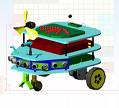
tutorial membuat robot cerdas image Bagaimana cara membuat robot-robot itu agar bisa hebat & cerdas? Dalam kesempatan ini akan dijelaskan langkah-langkah membuat robot cerdas
Tahap-tahap pembuatan robot

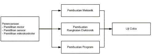
Secara garis besar, tahapan pembuatan robot dapat dilihat pada gambar berikut:
tutorial membuat robot cerdas tahapan pembuatan
  1. Perencanaan, meliputi: pemilihan hardware dan design.
  2. Pembuatan, meliputi pembuatan mekanik, elektonik, dan program.
  3. Uji coba.

1. Tahap perencanan

Dalam tahap ini, kita merencanakan apa yang akan kita buat, sederhananya, kita mau membuat robot yang seperti apa? berguna untuk apa? Hal yang perlu ditentukan dalam tahap ini:
  • Dimensi, yaitu panjang, lebar, tinggi, dan perkiraan berat dari robot. Robot KRI berukuran tinggi sektar 1m, sedangkan tinggi robot KRCI sekitar 25 cm.
  • Struktur material, apakah dari alumunium, besi, kayu, plastik, dan sebagainya.
  • Cara kerja robot, berisi bagian-bagian robot dan fungsi dari bagian-bagian itu. Misalnya lengan, konveyor, lift, power supply.
  • Sensor-sensor apa yang akan dipakai robot.
  • Mekanisme, bagaimana sistem mekanik agar robot dapat menyelesaikan tugas.
  • Metode pengontrolan, yaitu bagaimana robot dapat dikontrol dan digerakkan, mikroprosesor yanga digunakan, dan blok diagram sistem.
  • Strategi untuk memenangkan pertandingan, jika memang robot itu akan diikutkan lomba/kontes robot Indonesia/Internasional.

2. Tahap pembuatan

Ada tiga perkerjaan yang harus dilakukan dalam tahap ini, yaitu pembuatan mekanik, elektronik, dan programming. Masing-masing membutuhkan orang dengan spesialisasi yang berbeda-beda, yaitu:
  • Spesialis Mekanik, bidang ilmu yang cocok adalah teknik mesin dan teknik industri.
  • Spesialis Elektronika, bidang ilmu yang cocok adalah teknik elektro.
  • Spesialis Programming, bidang ilmu yang cocok adalah teknik informatika.
Pembuatan mekanik
Setelah gambaran garis besar bentuk robot dirancang, maka rangka dapat mulai dibuat. Umumnya rangka robot KRI terbuat dari alumunium kotak atau alumunium siku. Satu ruas rangka terhubung satu sama lain dengan keling alumunium. Keling adalah semacam paku alumunium yang berguna untuk menempelkan lembaran logam dengan erat. Rangka robot KRCI lebih variatif, bisa terbuat dari plastik atau besi panjang seperti jeruji.
Pembuatan sistem elektronika
Bagian sistem elektronika dirancang sesuai dengan fungsi yang diinginkan. Misalnya untuk menggerakkan motor DC diperlukan h-brigde, sedangkan untuk menggerakkan relay diperlukan saklar transistor. Sensor-sensor yang akan digunakan dipelajari dan dipahami cara kerjanya, misalnya:
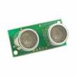
  1. Sensor jarak, bisa menggunakan SRF04, GP2D12, atau merakit sendiri modul sensor ultrasonik atau inframerah.
  2. Sensor arah, bisa menggunakan sensor kompas CMPS03 atau Dinsmore.
  3. Sensor suhu, bisa menggunakan LM35 atau sensor yang lain.
  4. Sensor nyala api/panas, bisa menggunakan UVTron atau Thermopile.
  5. Sensor line follower / line detector, bisa menggunakan led & photo transistor.
Berikut ini gambar sensor ultrasonik, inframerah, UVTron, dan kompas:
tutorial membuat robot cerdas srf 04tutorial membuat robot cerdas gp2d12kompas CMPS03
Pembuatan sistem elektronika ini meliputi tiga tahap:
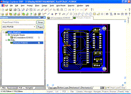
  • Design PCB, misalnya dengan program Altium DXP.
  • Pencetakan PCB, bisa dengan Proboard.
  • Perakitan dan pengujian rangkaian elektronika.
tutorial membuat robot cerdas design pcb
Pembuatan Software/Program
Pembuatan software dilakukan setelah alat siap untuk diuji. Software ini ditanamkan (didownload) pada mikrokontroler sehingga robot dapat berfungsi sesuai dengan yang diharapkan.
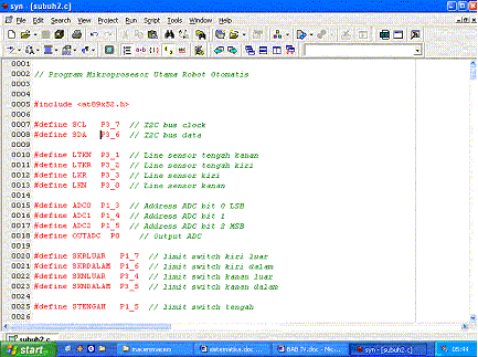
tutorial membuat robot cerdas pemrograman
Tahap pembuatan program ini meliputi:
  1. Perancangan Algoritma atau alur program
    Untuk fungsi yang sederhana, algoritma dapat dibuat langsung pada saat menulis program. Untuk fungsi yang kompleks, algoritma dibuat dengan menggunakan flow chart.
  2. Penulisan Program
    Penulisan program dalam Bahasa C, Assembly, Basic, atau Bahasa yang paling dikuasai.
  3. Compile dan download, yaitu mentransfer program yang kita tulis kepada robot.

3. Uji coba

Setelah kita mendownload program ke mikrokontroler (otak robot) berarti kita siap melakukan tahapan terakhir dalam membuat robot, yaitu uji coba.
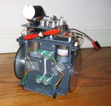
tutorial membuat robot cerdas contoh robot cerdasarena-lomba-krci

arena kri
.
Bacaan selanjutnya: